FIELD: machine building.
SUBSTANCE: group of inventions refers to the area of vibration damping of the booster working blades and the compressor of fifth generation aviation gas turbine engines. Fastening points for rotor blades of low and high pressure compressor rotors for fifth generation aircraft engines, made in the form of an annular protrusion on the inner and outer surfaces, made in the form of a barrel of rotors of the low and high pressure compressor, in which an annular profiled groove is made from the side of the outer surface of the barrel, in which the dovetail type locks are fixed with working blades with platforms, in the annular groove in diametrically opposite places, grooves are made with such a width and length in the tangential direction, so that the blade lock with a rectangular transverse radial section with depth can be accommodated therein, equal to the depth of the annular groove, and in the grooves and notches in the platforms locks are fixed, limiting the displacement of the blades in the tangential direction, with the outer diameter of the impeller, measured by locks, equal to the outer diameter, measured by the platforms of the blades, characterized in that the annular shaped groove is made with a conical bottom, the axis of the conical bottom surface coincides with the longitudinal axis of the rotor of the compressor of low and high pressure, and the angle at the apex of this cone is chosen from the condition of creating the required value of preload between the padlocks and the elastic hysteresis element, providing support therefor, and the radial cross section of the annular profiled groove has the shape of a dovetail, connected at the base with a trapezium with vertical side walls, the height of the trapezium, along which it is connected to the dovetail figure, is equal in mm 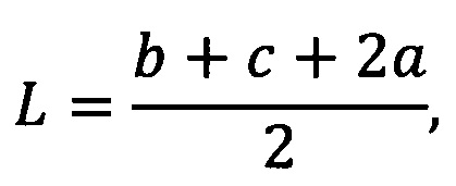 where b is the larger base of the dovetail figure, c is its smaller base, a - the value by which the trapezoid stands for the magnitude of the larger base of the dovetail figure, equal in mm
 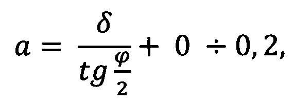 where δ - the tension in mm between the padlocks and the elastic hysteresis element, ϕ - the angle at the top of the cone bottom of the annular profiled groove, so that in one of the side walls of the protrusion of the attachment of working blades formed annular process groove with the greatest height, measured in a radial cross section equal in mm h=δ+H+0÷0.2, where H is the greatest height of the transverse radial section of the annular intermediate spacer, and the annular intermediate spacer is made of two diametrically opposed semirings with a transverse radial section in the form of a trapezoid - a truncated wedge, with the greatest height H, the width equal to or smaller than the width of the smaller base of the dovetail ring shaped grooves, and the angle of the wedge - half the angle of the wedge cone, equal to
  at the end with a smaller thickness of each semiring, two semicircular technological grooves or three such grooves are made at its ends, in this case one of the grooves is located in the middle part of the semiring, and the annular intermediate spacer is installed on the bottom of the annular profiled groove in such a way that its end with the notches is in contact with the side of the protrusion of the blade attachment point, in which there is no technological groove, between the annular intermediate spacer and the locks installed in the grooves and the locks of the rotor blades with radial tension δ there is a ring elastic hysteresis element with a width measured in the direction of the longitudinal axis of the rotor, equal to or less than the width of the smaller base of the dovetail of the annular profiled groove made up of one, two or more ring parts equidistant around the circumference, and between the ends of these parts there are gaps, the magnitude of which is either zero or equal to or less than half the permissible total value of the relative working displacements in the circumferential direction of the ends of this part of the ring and equal to 0.2÷0.5 mm, and between the outer surface of the barrel and the platform of each blade, as well as between the ends of the platforms of the adjacent blades and the counter ends of the platforms of the blades and locks, there are gaps, the value of which is limited by the values of the allowable displacement of the blade under the action of static and dynamic working loads, and under the platforms of the blades between the ends of the locks fixed in the recesses of the annular profiled groove, and the ends of the padlock locks, as well as between the ends of the padlock locks with tension along the annular elastic hysteresis element, the ends of the locks fixed in the recesses in the annular profiled groove, padlocks locks and platforms thereof are fitted with elastic hysteresis or elastic elements, and the values of these tensions are chosen in such a way that, when the blades oscillate, elastic mutual slippage occurs with dry friction of the contacting elements, four, six, or more circumferential locks in the annular groove are fixed in the grooves, and the sides of the locks fixed in the grooves in the annular profiled groove, on the part of its length, at the bottom of the ring groove, they are cut off and form an intake wedge, and four or six holes are made in the side wall with the technological groove of the protrusion of the attachment of blades, two of which are located in the areas of the ends of the semirings of the intermediate spacer, and when six holes are made, one more in the area of the middle part of each semiring, and into these holes the plugs are pressed in into the annular intermediate spacer until tight, and all the rubbing surfaces of the parts of the proposed attachment point are covered with a wear-resistant coating.
EFFECT: reliability of fastening and high-performance damping of the blades on all dangerous low forms of oscillations, with an allowable increase in the mass of the rotors and the number of their parts, is ensured.
11 cl, 20 dwg
| Title | Year | Author | Number |
|---|---|---|---|
| PLACE OF MOUNTING OF WORKING BLADES OF BOOSTER ROTORS AND COMPRESSOR OF AVIATION ENGINES OF FIFTH GENERATION; BOOSTER ROTOR AND ROTOR OF HIGH PRESSURE COMPRESSOR OF FIRST GENERATION AVIATION ENGINE, WITH WORKING BLADES, FIXED WITH HELP OF SWALLOWTAIL TYPE LOCKS IN RING GROOVES OF THESE DEVICES; METHOD OF ASSEMBLING PLACE OF MOUNTING WORKING BLADES OF BOOSTER ROTORS AND COMPRESSOR | 2016 |
|
RU2662755C2 |
| ROTOR OF AIRCRAFT GAS-TURBINE ENGINE COMPRESSOR WITH TWIN OF BLISKS AND TWIN OF BLISK WITH CLASSIC IMPELLER AND WITH TWIN OF CLASSIC IMPELLER WITH IMPELLER WITH FOURTH-TO-SIXTH STAGE WITH DEVICES FOR DAMPING VIBRATIONS OF WORKERS OF THESE CLIPS AND IMPELLERS, FAN ROTOR AND BOOSTER ROTOR WITH DEVICE FOR DAMPING OF VIBRATIONS OF WORKING WIDE CHORD BLADES OF FAN, TWIN ASSEMBLY METHOD WITH DAMPER DEVICE | 2016 |
|
RU2665789C2 |
| AXLE COMPRESSOR BLISK AND ROTOR OF LOW-PRESSURE COMPRESSOR OF AIRCRAFT GAS TURBINE ENGINE | 2019 |
|
RU2740442C2 |
| AIRCRAFT TURBOJET ENGINE FAN ROTOR WITH LONG WIDE-CHORD HOLLOW BLADES WITH DAMPERS | 2019 |
|
RU2727314C1 |
| GAS TURBINE ENGINE LOW PRESSURE COMPRESSOR ROTOR IMPELLER (VERSIONS) | 2015 |
|
RU2603379C1 |
| GAS TURBINE ENGINE LOW PRESSURE COMPRESSOR ROTOR IMPELLER (VERSIONS) | 2015 |
|
RU2603380C1 |
| GAS TURBINE ENGINE LOW-PRESSURE COMPRESSOR ROTOR IMPELLER (VERSIONS) | 2015 |
|
RU2611497C1 |
| LOW-PRESSURE COMPRESSOR OF GAS TURBINE ENGINE OF AVIATION TYPE | 2016 |
|
RU2614709C1 |
| AUTOMATIC DEVICE FOR THERMOMECHANICAL CONTROL OF RADIAL GAP BETWEEN ENDS OF ROTOR AND STATOR BLADES OF COMPRESSOR OR TURBINE OF GAS TURBINE ENGINE | 2018 |
|
RU2691000C1 |
| TURBOJET ENGINE LOW-PRESSURE COMPRESSOR SECOND STAGE ROTOR IMPELLER (VERSIONS) | 2015 |
|
RU2603383C1 |

