FIELD: optoelectron devices. SUBSTANCE: the catadioptric lens has the first collecting lens in the rays path, whose second surface in the central part has a mirror reflecting coating, diverging meniscus lens with the concavity facing the object, ring-shaped reflecting coating, second collecting lens cemented to the first surface of the diverging meniscus lens, and a light filter installed after the meniscus lens, the following relations should be satisfied: 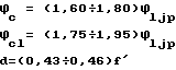 , where Φc- focal power of field aberrations compensator; Φcl - focal power of second collecting lens; Φljp - focal power of catadioptric lens; d - distance between countermirror and second collecting lens. f′ - image-side focal distance of catadioptric lens. The first collecting lens may be made convex-concave, and the countermirror may be flat. EFFECT: improved quality. 2 cl, 1 dwg, 8 tbl
| Title | Year | Author | Number |
|---|---|---|---|
| FAST CATADIOPTRIC OBJECTIVE | 1996 |
|
RU2093869C1 |
| CATADIOPTRIC LENS | 2001 |
|
RU2192027C1 |
| IR MIRROR-LENS OBJECTIVE | 2005 |
|
RU2288493C1 |
| TELESCOPIC SYSTEM FOR INFRA-BED RADIATION (VARIANTS) | 1996 |
|
RU2093870C1 |
| LIGHT-POWERED MIRROR-LENS OBJECTIVE | 2004 |
|
RU2261461C1 |
| INFRARED MIRROR-LENS OBJECTIVE WITH DOUBLE FIELD OF VIEW | 2005 |
|
RU2292066C1 |
| HIGH APERTURE-RATIO CATADIOPTRIC LENS | 1995 |
|
RU2091834C1 |
| STEP-VARYING-LENGTH OBJECTIVE LENS | 1996 |
|
RU2112256C1 |
| OBJECTIVE | 1996 |
|
RU2106003C1 |
| PHOTOGRAPHIC OBJECTIVE | 2000 |
|
RU2183339C1 |

