FIELD: electricity.
SUBSTANCE: method for identifying a steady-state alternating current in a conductor by means of a closing reed switch and a microprocessor, in which, in the laboratory, the first closing reed switch is placed in the inductor (CI) so that their longitudinal axes coincide, then alternating current is applied to the CI, gradually increasing it to current  , where
  is the smallest current in the CI at which the reed switches (contact closure) occurs,
  is the current amplitude, its value
  is measured, the time
  of the closed state of the reed contacts from the moment of action (short-circuiting) to the moment of reset (opening) of contacts at the first measurement and the current return
  , wherein the reed switch is returned to its original position, further, the current is increased to I2>I1,
  is measured (
 is the magnitude of the current amplitude for the second measurement) and time
  from the moment of action to the reset at this measurement, then the current is increased to I3>I2,
  is measured (
 is the magnitude of the current amplitude for the third measurement) and time
  from the moment of action to reset, then the current is increased to I4>I3 and so on, repeating previous operations before In>In-1, where
  , n-1 is number of necessary measurements of time and current
  and
and  (i= 1, 2…n), N is current multiplicity in the IC with respect to the minimum current of the reed switch
  , n=30÷40, N=50÷100, then the dependence of the current amplitude in the conductor on the time of the closed state
  from the moment of operation of the first reed switch to its return
 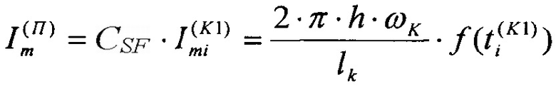 is constructed, and the obtained dependence is entered in the microprocessor (in (1), where
  is the current amplitude in the conductor, CSF is the current scale factor in IC at the current in the conductor, and h is the distance from the conductor to the contacts of the reed switch, ωK is the number of turns in the first IC, lk is the length of the first IC), then reed switch is at the design point close to the conductor and when it is triggered with microprocessor the time
  of closed state of the reed switch is measured, and according to (1) dependence the amplitude of the
  is determine, characterized in that at each i-m measurement
  and
and  in the inductor is measured and also i-th actuating current
  of reed, after all the measurements a dependency
  (2) is built, the dependence (2) and
  are introduced in the microprocessor, then in the laboratory in the second IC the second normally open reed switch is put so that their longitudinal axes coincide, then the AC voltage U(K2) is supplied, the angle ψ between the supplied voltage U(K2) and current
  flowing in the second IC is determined, then gradually increasing U(K2) to increase of current in IC to
  where
where  is the smallest current flowing in IC, at which the actuation of the second reed switch (contact closure) occurs,
  is the current amplitude, the value of the
  time of
  closed state of contacts of the second reed switch from the time of action to reset (contact opening) and the reset current
  at which the reed switch returns to its original position are measured, then U(K2) is increase to the increase of current in IC to
 is measured, where
  is the current amplitude, time
  from moment of action to reset, and the actuating current
  then U(K2) is increased to the increase of the current in IC to
 is measured, where
  is the current amplitude, time
  from moment of action to reset, and the actuating current
  , then U(K2) is increased to increase of current in IC to
  and so on, repeating the previous operations to
  , where
  is the current in IC when the voltage applied U(K2)=120, k-1 is the number of required measuring of time and currents
  ,
,  and
and  (i=1, 2…k), k=10÷15, further the dependence of the current
  amplitude and of the actuating current operation in IC from time of closed state
  from the moment of action of the reed switch to the moment of its reset
  is built, and the dependencies are entered,
  and ψ in the microprocessor, then the first reed switch is set in close proximity to the conductor, and the second IC with the second reed switch is connected to the terminals of the secondary winding of the voltage transformer, both of the reed switches can operate in parallel, therefore, the microprocessor can simultaneously perform the following operations, with the closure of the contacts of the first reed switch installed in close proximity to the conductor, astronomical time
  and
and  is recorded, at short-circuiting and opening of its contacts occurred, respectively, then using a microprocessor the current in the conductor
  is found from the dependence (2) after
  , at which the reed switch has closed contacts, the time
  and
and  is found from formulae
  and
and  where
where  and
and  are the time intervals from the transition of the sinusoid through zero to triggering and from the moment of reset until the next transition through zero, respectively, then the astronomical time of transition of the current sinusoid through zero by the formula
  is determined, at the actuation of the second reed switch with a microprocessor astronomical time
  is recorded, the time
  of closed state of the reed switch is measured, upon opening the second reed switch contacts in IC with a microprocessor astronomical time
  is recorded and after dependencies (3) the current amplitude
  and of the actuating current
  values are determined, then the time
  and
and  is found of formulae
  and
and  where
where  and
and  are the time intervals from the transition of the sinusoid through zero to triggering and from the moment of reset until the next transition through zero, respectively, and the astronomical time of transition of the current sinusoid through zero in the second IC is determined by the formula
  then the transition of a voltage sinusoid through zero is defined by the formula
 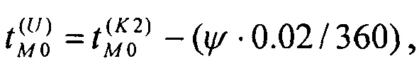 this time is remembered until the determination of the next transition of voltage through zero, then using a microprocessor phase of steady-state AC current in the conductor is determined relative to the voltage according to the formula
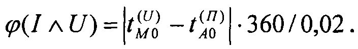
EFFECT: expansion of the field of use due to the determination of the phase of the steady-state alternating current by fixing the astronomical time of action and reset moments of reed switches, determining the moments of transition of the current and the voltage sinusoid through zero used as the reference point.
2 dwg
КПР - CSF
:
СР –
П –
 :
:
К –
В –
:
М –
А –
| Title | Year | Author | Number |
|---|---|---|---|
| METHOD OF THE AC VOLTAGE IDENTIFICATION IN THE CONDUCTOR WITH THE HELP OF THE CASTING HERCON | 2015 |
|
RU2618795C1 |
| METHOD OF DETERMINING CURRENT DIRECTION | 2023 |
|
RU2815306C1 |
| MEASURING METHOD OF CURRENT IN ELECTRIC CONDUCTOR BY MAGNETIC REED RELAYS | 2008 |
|
RU2397499C2 |
| METHOD FOR MEASURING FAULT CURRENT | 2014 |
|
RU2575139C1 |
| INDUCTION MOTOR OVERLOAD PROTECTION APPARATUS | 0 |
|
SU961027A1 |
| METHOD OF CURRENT MEASUREMENT | 2008 |
|
RU2377579C2 |
| METHOD OF CURRENT MEASUREMENT IN CONDUCTOR BY SEALED REED RELAYS | 2013 |
|
RU2540260C1 |
| DEVICE FOR CURRENT PROTECTION OF DAMAGE IN AC MAINS WITH DEPENDENT TIME DELAY | 0 |
|
SU803075A1 |
| METHOD FOR MEASURING FAULT CURRENT | 2014 |
|
RU2554282C1 |
| METHOD OF GROUP PRODUCTION OF REED SWITCHES WITH NITRIDED CONTACT PADS | 2020 |
|
RU2739583C1 |

