FIELD: electronic engineering. SUBSTANCE: method involves variation of S-type element turn-on voltage  by means of control signal:
  , where U
 is S-type element turn-on voltage at
  ; variation of supply voltage obeying law Es= Eno±ΔUon, where Eso is initial value of supply voltage; determination of negative differential resistance at
 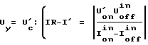 , where U
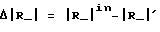
 , this being followed by determination of negative differential resistance increment
  obtained at initial control voltage U
 :
:  . Then current-setting resistor value is varied by ΔRo according to dependence
 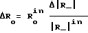 , where R
| Title | Year | Author | Number |
|---|---|---|---|
| METHOD AND DEVICE FOR CHECKING PRESET NEGATIVE DIFFERENTIAL RESISTANCE OF S-TYPE ELEMENT | 1992 |
|
RU2105989C1 |
| METHOD FOR THERMAL STABILIZATION OF ACTIVE INDUCTANCE COIL | 1990 |
|
RU2017326C1 |
| DEVICE WITH S-TYPE CURRENT-VOLTAGE CHARACTERISTIC | 0 |
|
SU1826125A1 |
| ATMOSPHERIC IONS COUNTER | 0 |
|
SU1795402A1 |
| SINE OSCILLATOR | 1991 |
|
RU2012124C1 |
| DISPLACEMENT METER | 2001 |
|
RU2213934C2 |
| GENERATOR OF SIGNAL FOR TURNING JAMMING ON | 1993 |
|
RU2122281C1 |
| FREQUENCY MULTIPLIER | 1990 |
|
RU2017320C1 |
| METHOD FOR DETERMINATION OF CORROSION RESISTANCE OF MATERIALS | 1991 |
|
RU2016401C1 |
| SELECTIVE AMPLIFIER | 2012 |
|
RU2519446C2 |
