FIELD: transport.
SUBSTANCE: invention relates to aircraft and space engineering, namely to steering machine electro-hydraulic booster. Proposed booster comprises electromechanical converter with its shaft accommodating spring-loaded control crank with two slide-valve plungers attached to crank ends. Plungers are arranged in hollow shafts of pump driven gears. Shaft walls have through radial throttling orifices partially overlapped by slide-valve plungers and communicated with electro-hydraulic booster chambers. Shafts of said pump driven gears are furnished with circular grooves arranged in the zone of through radial throttling orifices. Said through radial throttling orifices have tapered chamfers arranged on the side of circular grooves. Edges of said chamfers are located inside circular grooves. Note here that depth of conical chamfer ℓ and angle α of inclination of chamfer generating line to the axis of through radial throttling orifice are defined subject to the following formulas: 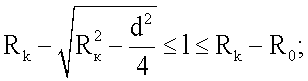
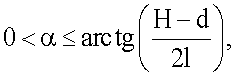 where ℓ is chamfer depth; α is angle of inclination of chamfer generating line to the axis of through radial throttling orifice; Rk is circular groove cylindrical surface radius; Ro is radius of shaft driven gear axial orifice cylindrical surface; d is diametre of through radial throttling orifice; H is groove width.
EFFECT: increased sensitivity of steering machine electro-hydraulic booster.
3 dwg
| Title | Year | Author | Number |
|---|---|---|---|
| ELECTRIC HYDRAULIC AMPLIFIER FOR STEERING MACHINE | 2007 |
|
RU2360150C2 |
| SERVO UNIT | 2005 |
|
RU2293687C2 |
| ACTUATOR | 1998 |
|
RU2131827C1 |
| STEERING ENGINE | 2003 |
|
RU2240260C2 |
| SERVO UNIT | 1990 |
|
RU2034747C1 |
| STEERING ASSEMBLY | 2006 |
|
RU2346229C2 |
| COMBINATION ACTUATOR | 2003 |
|
RU2245462C1 |
| COMBINATION DRIVE | 2001 |
|
RU2190783C1 |
| PROCESS OF ASSEMBLY OF CONTROL ACTUATOR | 2001 |
|
RU2194239C2 |
| METHOD FOR ASSEMBLING OF CONTROL ACTUATOR | 2001 |
|
RU2187779C1 |

