FIELD: pipelines.
SUBSTANCE: it can be used in various industries, where the technological processes includes mixing. The method for mixing the medium transported through the pipeline with a known change in the flow rate of the medium includes the medium transportation through the pipeline, which is formed before mixing by introducing into it by injection, injection with a known change in the flow rate of an additional component transported to the point of entry into the pipeline through the component line, then mix a component with a medium with a limited intensity in a device placed on the pipeline for mixing using the energy of the medium flow in the pipeline, according to the invention, the intensity of the input of the component into the pipeline flow is regulated by distributing it in the medium in a trickle or trickles, changing their diameter, quantity, regardless of the flow rate of the component in component pipeline; further, the local concentration of the component introduced into the medium is reduced by its intermediate mixing to a mixing device with the ability to control the intensity of intermediate mixing, while the pressure drop on the intermediate mixing can be set in the range not exceeding the difference between the allowable and actual pressure drop on the mixing device; when using the technological process that comprises mixing of the medium with the component introduced into it, the listed operations are adapted; if a preliminary theoretical assessment of the quality of mixing of the medium with the component introduced into it is carried out, one or both of the ratios (1)-(1) * are used for the component insoluble in the medium, establishing the relationship of the emerging dispersion of the component introduced into the medium, namely, the average and maximum diameter of the droplets of the component formed due to the energy of the component flow when it is injected into the medium flow in the pipeline, depending on the intensity of the input of the component and its distribution parameters, the diameter of the stream / streams, surface tension, as well as the medium parameters, density, viscosity:
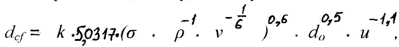

where dcf and dmax - the average and maximum diameter of the drops of the component, respectively, formed during the injection of the component into the environment;ν and,ρ respectively, the viscosity, cSt, and the density of the medium, kg/m3 ;σ - surface tension on the phase boundaries of the components - medium, N/m; u=uc - un cosα , in which uc is the initial speed of the trickle, m/s; un is flow velocity, m/s; α is the angle between the directions of injection of the jet and the flow of the medium in the pipeline; do is the initial diameter of the streams, m; k=0,9÷ 1,1 - the correction factor, - can be refined experimentally for a specific technological process during the listed operations of the method, without clarification, it is taken equal to the value k=1; in this case, according to the flow rate of the component in the component pipeline and the flow rate of the component in the stream, the number of streams of the component is determined, at which the total flow rate of the streams will be equal to the flow rate of the component in the component pipeline. The device for stirring the medium transported through the pipeline uses a device for mixing the medium, which, according to the invention, includes a device for mixing the medium; a throttle device placed in front of it, which includes a housing with a damper installed in it with/without perforation of a round/elliptical/petal profile and a drive for changing the cross section of the medium flow in the pipeline in the radial direction from the symmetry axis of the pipeline; a distributor for introducing a component into the flow of the pipeline medium, which is supplied to the distributor along the component pipeline, while the distributor, which is mounted on the side surface of the pipeline/coil through a branch pipe with/without a shut-off valve, includes a cylindrical body, a component input element with a steering drive for converting the rotational movement of the handwheel into a translational element of the component input for its immersion/extraction into the pipeline under pressure, while the input element of the component with the handwheel drive is coaxially mounted in the cavity of the distributor housing, and the distributor is connected to the component pipeline through the side fitting on the distributor housing, the input element component is designed in the form of a perforated cylindrical branch pipe; a partition is installed in the distributor body, coaxially below the side fitting, with/without a cut on the side and a hole in the centre for the passage of the branch pipe of the input element, which separates the perforation on the input element branch pipe along its outer surface into the upper and lower parts and ensures their communication through the cavity of this branch pipe; the perforation areas of the upper and lower parts of the component input element are regulated by changing its working position with a handwheel drive; the distributor is additionally equipped with fittings/faucet/valve that regulates the flow rate of the component introduced into the pipeline, which is mounted either on or in front of the nozzle distributor or on the component pipeline; if the partition is made with a cut, additionally at the level of the cut to purge the perforation, a purge cock with a bypass with/without filter(s) and a cock/valve connecting the purge cock and the component line can be installed on the side surface of the distributor housing, while the bypass outlet is connected to the distributor body at the level of the partition cut; additionally, a drain cock is installed on the distributor body closer to the upper border of the partition; the purge cock can feature the function of emptying the distributor cavity, i.e. three-way; the number of perforation holes with their selected diameter is determined at the maximum flow rate of the component through the component pipeline based on the condition of the minimum and maximum speed of its injection into the formed medium in the pipeline, required for the technological process, which uses mixing; based on this condition, the pump for pumping the component through the component pipeline is also selected, if the device is supplied with it; the device can additionally be equipped with replaceable input elements with various perforation of its lower part with holes to adjust it to a specific technological process in which the device is used; the appropriate version of the input element for the most efficient implementation of the technological process is determined empirically; if the formed medium is mixed with an insoluble component, the diameter of the perforation hole in the lower part of the input element is selected depending on the average diameter of the droplets formed when the component is injected into the medium flow through the distributor input element, the initial speed of the jets, the flow parameters in accordance with the following formula:

where do is the diameter of the perforation/initial diameter of the streams, m; dcf is the average diameter of the component drops, respectively, formed during the injection of the component into the environment, m;ν and ρ is, respectively, the viscosity, cSt, and the density of the medium, kg/m3; σ is surface tension on the phase boundaries; component - medium, N/m; u=uc - un cosα , where uc is the initial speed of the trickle, m/s; un is flow velocity, m/s; α is the angle between the directions of injection of the jet and the flow of the medium in the pipeline; k=0,9÷1,1 - the correction factor - can be refined experimentally for a specific technological process when implementing the listed operations of the method; it is taken equal to the value k=1 without clarification.
EFFECT: high quality of the mixing product, makes it possible to intensify the ongoing processes, increase their reliability, and allows expanding the scope of static mixing devices for mixing various media in order to achieve the most efficient technological process.
4 cl, 2 dwg, 3 tbl
| Title | Year | Author | Number |
|---|---|---|---|
| METHOD FOR MIXING MEDIUM TRANSPORTED THROUGH PIPELINE AND DEVICE FOR CARRYING OUT SAID METHOD | 2019 |
|
RU2744373C1 |
| METHOD OF DIFFERENT MEDIA PUMPING THROUGH PIPELINE AND DEVICE FOR ITS IMPLEMENTATION | 2014 |
|
RU2610117C2 |
| FILTER | 2023 |
|
RU2815377C1 |
| DEVICE FOR SAMPLING LIQUID FROM THE PIPELINE | 2021 |
|
RU2777492C1 |
| METHOD OF SAMPLING FLUID FROM GAS-LIQUID FLOW IN PIPELINE AND DEVICE FOR ITS IMPLEMENTATION | 2014 |
|
RU2616780C2 |
| METHOD FOR SAMPLING FROM MEDIA SUBJECT TO DELAMINATION AND DEVICE FOR ITS IMPLEMENTATION | 2019 |
|
RU2746878C1 |
| METHOD FOR SAMPLING DEMIXING-PRONE MEDIA AND DEVICE THEREFOR | 2014 |
|
RU2580724C2 |
| METHOD OF AND DEVICE FOR INTRODUCTION OF CHEMICAL REAGENT INTO FLOW OF LIQUID IN PIPELINE | 2006 |
|
RU2308639C1 |
| METHOD OF CHEMICAL INJECTION IN WELL AND RELATED DEVICE FOR IMPLEMENTATION THEREOF | 2008 |
|
RU2387808C1 |
| METHOD AND DEVICE FOR SAMPLING LIQUID FROM PIPELINE | 2005 |
|
RU2309391C2 |

